
New Functionality of nanoCAD
A new setting Scale Block Reference (PARAMS – Main options tab – Edit section), which allows you to enable and disable block scaling. By default, the option is enabled, the block is scaled when the symbol scale changes.

The design has been updated for the Formation of a package of files (ETRANSMIT) dialog and its work has been optimized. The file type icons have been changed, and the ability to select multiple files using the SHIFT and CTRL keys has been added.

The possibility has been added to set the accuracy of export (EXPORT) to STL (*.stl) format by specifying the maximum allowable distance between neighboring points (Max chord length).

For more convenient interaction with the interface, the icons of unused files in the External References (EXTERNALREFERENCES) functional toolbar have been changed
A new Constrained dimension (DCAUTO) command has been added to insert Parametric dimensions by one command (similar to MDIM). This command can only work in the sketch edit mode.
The Insert map by control points toolbar has been implemented for inserting a raster map underlay by control points. You can open the toolbar by opening the Map Underlay (MAPVIEW) dialog: on the Raster maps tab, select the required parameters, check the By control points box at the bottom of the dialog, and click the OK button.

Export
The GLB and GLTF formats have been added to the export command (EXPORT). These formats for 3D scenes and models have the following main advantages: small file sizes, fast loading and processing, full representation of the three-dimensional scene.
The possibility to specify Y axis (up) rotation settings has been added for exporting GLB and GLTF files:

Quick Properties Mini-Bar
A floating Quick Properties (QUICKPROPERTIES) mini-bar has been implemented for more convenient interaction with the interface.

When you click the

Settings button, the Customize Properties List dialog box appears, where you can specify properties for each object type to display in the floating bar.

Automatic Vector Correction
A new Vector Correction (AUTOVC) command has been implemented. The command allows you to correct geometric deviations made during construction or as a result of automatic and semiautomatic vectorization (tracing) for the following objects:
- line
- polyline
- arc
- circle
Automatic correction allows you to:
- delete objects smaller than the specified size
- restore contacts between objects
- “paste” fragments into a single object
- align lines along standard directions (UCS, Ortho-grid), if their deviations do not exceed the value specified by the user
- change the order of rounding the coordinates of drawing objects

Data Collection in case of Fatal Error
When critical errors occur in the program, the possibility to automatically collect data containing statistics and event chronology has been added using the ReportProblem command.
The command creates a folder specifying the time and forms a file package for transfer in it. After that, the user is prompted in the dialog box to add or remove files for sending. Then there are two options: you can report it as a ZIP archiveand save it on computer (Save report button) or send it by email in EML format (Send report button).
Batch File Processing
In the Batch Files Processing (BATCHPROCESS) utility in the standard default profile, one more processing stage has been added – Remove proxy-objects (RMPROXY). By default, the option is disabled. The command allows you to select the type of proxy objects to be removed (with graphics and/or without graphics).

The Add the current file automatically setting has been added to the list of selected files for batch processing:

By default, the setting is enabled and when you run the Batch File Processing (BATCHPROCESS) command, the current drawing is added to the Selected files list automatically.
You can now add to the Selected files list not only files with the DWG extension (drawing format), but also DWT (template format).
Sheet Set
The dialog has been added for setting up the Sheet List Table, in which you can specify the following parameters: table style, title text, table data (column settings), and also specify a previously saved sheet set or select sheets to include in the list.

Associativity of DST format files has been added. Now, documentation set files are automatically opened in nanoCAD and the Sheet Set Manager (SHEETSET) toolbar is launched simultaneously.
The possibility to move sheets inside the document set/group by simply dragging them has been added in the Sheet Set Manager (SHEETSET) toolbar.
The usability of the Rename & Renumber Sheet dialog box in the Sheet Set Manager (SHEETSET) toolbar by automatically selecting the Number field has been improved.
On the Sheet Lists tab of the Sheet Set Manager toolbar, the menu button

has been added for publication of selected sheets or the entire sheet set. The following output options are possible:
- publish to PDF
- publish to Plotter
- publish to DWF
- publish to DWFx
The publish of document set/sheet group/sheet set/sheet is also available in the Sheet Set tree context menu.
A file name suggested by default for a multi-sheet document when plotting now matches the name of the documentation set instead of the name of the first sheet.
Plot
The Create bookmarks option has been added to the Print as PDF and Internal PDF Plotter settings dialog to create bookmarks for sheets and named views in a PDF file.

The Include hyperlinks option has been added to the settings dialogs for Internal DWFx Plotter, Internal DWF Plotter, Internal PDF Plotter, Print as PDF. This option converts document hyperlinks into hyperlinks in a PDF file.
For all internal printers, the possibility to save plotting device settings as a separate file with the PC3 extension has been added for easy use on multiple computers.
The Use subfolder option has been added to the settings dialogs for all internal printers to create an additional directory with the format name (DWFx, DWF, EMF, PDF, or Raster) and save files to the created subfolder. The option is available when the Use predefined file name and Use document file folder modes are enabled.
The PC3 plotter settings file can now be located not only in the standard plot configuration file folder C:\Users\User_name\AppData\Roaming\Nanosoft AS\nanoCAD x64 25\PlotConfigs, but also in the directory where the DWG file itself is located.
Search for network plotters has been optimized. The time to connect to disconnected or “nonexistent” network plotters has been reduced to several seconds.
A new PARAMETERSCURLAYOUT command, which opens the Page setup dialog for setting up the plot settings for the selected sheet.
Tables
A new command Recalculate all tables in the drawing (RECALCTABLES) has been added. The command recalculates data in all tables in the drawing. When recalculating, auto-recalculation locks and report freezes are ignored. During recalculation, the Refresh reports and Recalculate options are applied.
The possibility to load tables (TABLE) from XLSX files without a pre-installed office suite has been implemented.
In nanoCAD Tables (TABLE), the following buttons for formatting text in cells have been added to the full editor interface: Underline, Strikeout, Overline, which allows you to edit the wording in several table cells at once.

Text
A new system variable MTEXTFIXED has been added, which determines the display of hard-to-read text objects during editing (small, large, or rotated text is considered hard to read):
- MTEXTFIXED = 0 (or 1) – the text is displayed in accordance with the size and rotation in the drawing;
- MTEXTFIXED = 2 (default value) – the text is displayed in a convenient size and in the horizontal direction.


The following combinations are now available for entering superscript and subscript characters in Multiline text (MTEXT):
- superscript – CTRL + UP ARROW
- subscript – CTRL + DOWN ARROW
The combinations also work in nanoCAD Tables (TABLE).
The following combinations are now available for formatting Single-line text (TEXT):
- strikeout text – %%K or CTRL + K
- underlined text – %%U or CTRL + U
- overlined text – %%O or CTRL + O
For all tools to create and edit Multiline text (MTEXT) and Single-line text (TEXT), the sequence and name of paragraph alignments have been brought to a unified form: Align left, Align center, Align right, Justified, Distributed.
The functionality of the Paragraph dialog, called from the Text Format (MTEXT) bar, has been expanded.

The following settings have been added:
- selection of tab type, as well as the number and positions of tabs, • indent options and values
- paragraph alignment
The settings for intervals before and after a paragraph and setting line spacing within a paragraph have been expanded.
A warning message has been added when entering invalid values of the overlap coefficient in the Hiding the Background (BACKGROUNDMASK) dialog.
Templates
The possibility to create a new document based on a specified DWT template file has been added to the nanoCAD

button.

The list of templates offered for selection in the menu is limited. To select another template not presented in the list, open the Choose template dialog or configure the Template Names List in the Template Usage section of the Options (OPTIONS) dialog.
The

Choose template (TEMPLATESDIA) command opens the Choose template dialog box with a list of file templates.

You can add or remove a template by selecting the appropriate command in the context menu. The order of templates can be changed by simply dragging and dropping.
Toolbars
The functions of the classic dialog Linetype Manager (STYLEEDITCMDCLASSIC) have been improved and implemented in the new

Linetypes (STYLEEDITCMD) toolbar. The linetype editor is located directly on the toolbar and allows you to quickly edit the selected linetype or create a new one.

The functions of the classic

Text Style (TEXTPROPSCMDCLASSIC) have been improved and implemented in the new Text Styles (TEXTPROPSCMD) toolbar.

Groups
When creating a duplicate group (a group containing the same set of objects as an existing group in the drawing) using the GROUP and -GROUP commands, an additional prompt has been added to the command line: “Group with the same objects already exists. Create a new group anyway?”.
The context menu for creating a group (GROUP) has been optimized. The Exploding a Group, Add to Group and Removing from the Group context menu commands are blocked when pre-selecting existing groups and individual objects.
In the Object Grouping (GROUPCMD) dialog, the mechanism for highlighting objects in the selected group on the screen has been changed. Now the Object Grouping dialog box does not close. When the Highlight option is enabled, the group whose line is selected in the dialog list is highlighted on the screen.

Dialog Updates
The Drawing Properties (DWGPROPS) dialog has been updated. The possibility to change the size of the dialog box, save the width of columns of the user properties table have been added, and the visual component has been improved.

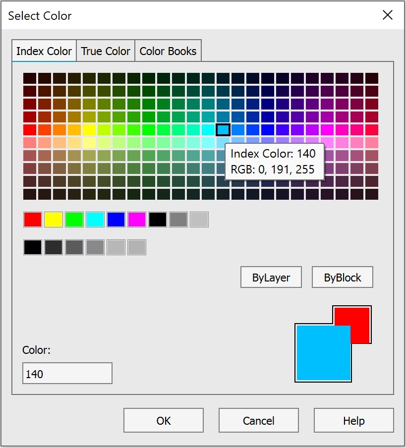
The Select Color (COLOR) has been updated. The function of saving the dialog’s position on the screen has been configured. Options for specifying a color by a sample of any point on the screen (with an eyedropper) and in the HSV color model have been added. The possibility to change the color number on the True Color tab using the arrows on the keyboard has been implemented.
The Hyperlink (HYPERLINK) dialog has been revised.

The Select Custom Arrow Block dialog has been updated.

The Point Style dialog has been updated.

Other Novelties
A new command Replace Block with Another Block (BLOCKREPLACE) has been added, which allows replacing all selected blocks with one specified block. The objects to be replaced can be pre-selected or specified in response to a command line prompt.
A new system variable OFFSETGAPTYPE has been added, which determines the type of external corners when constructing a polyline offset (OFFSET):
- OFFSETGAPTYPE = 0 (default value) – the offset lines are extended to form a corner;
- OFFSETGAPTYPE = 1 – at the intersections of the offset lines, a fillet is constructed with a radius equal to the offset distance;
- OFFSETGAPTYPE = 2 – at the intersections of the offset lines, a chamfer is constructed, the perpendicular distance from each chamfer to the corresponding vertex on the original object is equal to the offset distance.

The Intersection snap for spline self-intersection points has been added (SPLINE).
In the External references (EXTERNALREFERENCES) toolbar, for more convenient interaction with the interface, the following icons of external reference statuses have been added: File not found, Unloaded, Unreferenced.

The possibility to change the Transparency (TRANSPARENCY) of the background of raster images in TIF (TIFF)format has been added.
The new command

Sending by Email (ETRANSMITDWG) has been added to the

nanoCAD button. The command generates an EML file to send the current drawing via email.
The informational tips have been added for buttons in the Formation of a package of files (ETRANSMIT) dialog, for layer parameter icons in the Layers (LAYERSQUICK) toolbar.
The possibility to simultaneously open/hide all property groups has been added in the Properties (INSPECTOR) toolbar. To do this, click the

or

button in the name line of any group while holding down the SHIFT key.
The method of editing dimensions by double-clicking has been changed. Now, when the Dimensions option is disabled (in the Settings nanoCAD (PARAMS) dialog, Main Options tab, Edit section – By double-click), the command for editing multi-line text (MTEDIT) is called.

Wordings for warning messages about largenumber of external references (XREF) have been corrected.
The descriptions of subsections of the System settings section of the Options (OPTIONS) dialog, clarifying the possibilities for changes to take effect.
The Save Layout as… (LAYOUTTOTEMPLATE) item has been added to the context menu of the Model and Layout tabs.
Changing the Multiple lines mode has been blocked when editing a multi-line attribute in the Block Attribute Manager (BATTMAN).
The “Don’t show again” messageboxes section has been added in the Options (OPTIONS) dialog box, where you can manage the display of some warnings.

Visual presentation of information, warning and error messages has been optimized.
The program behavior when assigning color and covering (COVERINGBROWSER) has been optimized. Now you can assign color or covering only to the entire solid or its face, but not to a vertex or edge, about which a warning message has been added.
Fixed bugs that caused the program to close
The program crash when selecting WIPEOUT object while running the LIST command has been fixed.
The bug that caused the program to crash when opening a file containing a block with a z-coordinate spread has been fixed.
The bug that caused the program to freeze and crash when copying the numbered list format in multiline text (MTEXT) has been fixed.
The crash that occurred when adding custom color albums (*.acb) containing more than 10 colors in a section has been fixed.
The program crash when switching the workspace (model/layout) while executing commands has been fixed.
The program crash when updating the Layers (LAYERSQUICK) toolbar while adding a new layer has been fixed.
The bug that caused the program to hang when switching between layouts in a user file has been fixed.
The bugs that caused the program to hang in user files when switching between model space and paper space have been fixed.
The bug that caused the program to freeze and crash when autosaving a custom drawing has been fixed.
The program freeze when copying elements to the clipboard of objects in custom files has been eliminated.
The program crash when setting up the Status bar in the Customize user interface (INTERFACE) has been eliminated.
The program crash when starting text editing (MTEXT) on a locked layer through the Properties (INSPECTOR) toolbar has been fixed.
The bug that caused the program hang-up when working with the Intersection snap on splines and ellipses in user files has been fixed.
The program hang-up when adding hatching (HATCH) on user objects (ellipses, arcs, splines) using the Add: Pick points method has been fixed.
The program crash that occurred when copying multileaders (MLEADER) with blocks and changing their location Insertion point.
Plot Fixes
The bug has been fixed due to which the displacement and change of scale of drawing objects was observed when printing (PLOT) using the internal DWF/DWFxplotters.
The bug has been fixed due to which only the last sheet was printed when batch plotting (PUBLISH) to a multi-sheet file using the internal DWF/DWFx plotters.
The bug has been fixed due to which the Plot window did not close after plotting from the Preview window.
The bug has been fixed due to which bitonal rasters were not printed (PLOT) on the internal raster plotter when the Indexed raster type is selected.
The bug due to which rasters of the *.ecw format created by the internal raster plotter were not printed (PLOT) has been fixed.
The work of the button for switching workspace during plotting (PLOT) has been corrected.
The bug, where plot (PLOT) centering was not detected for documents created in third-party applications, has been fixed.
The bug, where the contents of viewports (VIEWPORTS) was not displayed when printing (PLOT) through the Internal PDF Plotter if there were a large number of viewports, has been fixed.
The printing (PLOT) of multiple areas using the Internal DWF Plotter has been improved. Now, when inserting multi-page DWF files, all sheets are inserted.
The bug, where the number 5 was crossed out when printing (PLOT), has been fixed.
The bug, where the lights and shadows configured in the model were not plotted, has been fixed.
Fixes in Work with Documents
The bug due to which a new document (NEW) was not created due to a missing template has bOPTIONSeen fixed. Now, if a template is missing or the path to the template is incorrectly specified in the Options (), a warning message is displayed and a document is created without a template.
The bug due to which, when selecting a template, the Subject and Comments fields were not displayed in the Select Template dialog, has been fixed.
The bug has been fixed due to which a new document was created when clicking the Cancel button in the Select template dialog.
The bug has been fixed due to which only a white background color was used when saving a drawing area to raster (RASTEROUT).
The bug that prevented export to *.dae format has been fixed.
The bugs that occurred when importing custom files in *.dgn format have been fixed.
The bug of exporting a layout to a model (EXPORTLAYOUT) for files created in Plant 3D has been fixed.
Fixes in Work with Layers
The bug due to which a warning message about renaming when selecting layer 0 appeared in the Layers (LAYERSQUICK) toolbar.
The work of the Layer Settings in the Layers (LAYERSQUICK) toolbar has been optimized. Now, when setting the Indicate layers in use option, it is not required to refresh the toolbar.
The bug due to which an unselected layer was deleted in a tree view in the Layers (LAYERSQUICK) toolbar has been fixed.
The bug due to which a color from color book files was replaced with an RGB value in the Layer manager (LAYERSQUICK) has been fixed.
The bug due to which the visibility of layers in a drawing was turned off when working with the Layer Translator (LAYTRANS) has been fixed.
The bug has been fixed due to which the first rows in the Translate from and in the Layer Translation Mappings table were selected by default in the Layer Translator (LAYTRANS).
The bug has been fixed due to which the visibility of layers was not turned on after conversion in the Layer Translator (LAYTRANS).
Fixes in Work with Tables
The bug has been fixed due to which there were errors in the display of text in a table (TABLE) inserted into a drawing as an external reference (ATTACH).
The bug has been fixed due to which actions with objects in a drawing containing empty tables (without rows and columns) were blocked.
The bug of saving drawings containing .dwg tables (DTABLE) with a break has been fixed.
Fixes of Scaling Bugs
The bug due to which scaling multiline text (MTEXT) would not change the custom height.
A warning message has been added when specifying a scale name (SCALELISTEDIT) that consists of spaces.
The bug has been fixed, due to which a field (FIELD) of a block attribute (ATT, BLOCK) would turn to text after changing the character scale.
The bug has been fixed, due to which resetting scales while opening a file, the metric scale list was replaced with an inch scale list.
The bug that caused a message about incorrect input to appear in the command line when setting the scale of the selected viewport in a paper space has been fixed.
Changes in the Composition of Commands
Commands for working with Databases have been moved to the new Storage module of the Point Clouds vertical application.
Project Manager
Errors in the Project Manager (NPC_PROJECT_MANAGER) have been fixed:
- freezing during import
- crash resulting from block renaming
- flight line shift
Import of point clouds of RCS format has been improved.
Crash when closing the program after importing a cloud has been fixed.
The DB connection panel has been improved (parameter checks, connection log, default DB connection mode, etc. appeared).


The format for storage of point survey time (was GPS time, now became GPS week).
The DB_UNDO/DB_REDO (semi-automatic cloud undo tool) commands have been added.
The POINTCLOUDSECTIONUCS system variable has been added, which allows you to manage specifying UCS when performing cloud sections.
Index vocabularies for all attributes have been added in the cloud storage core. All index vocabularies are displayed in the Point Cloud Info (NPC_INFO) dialog.
The procedure for constructing cloud detail levels in order to improve the visual perception of the transition from one detail level to another has been redesigned.
The problem of importing PTS files with normals has been fixed.
The possibility to undo and redo the creation of areas in the point cloud preview window during import has been corrected.
View Mode
View Mode (NPC_VIEWMODE) of point clouds has completely changed and is now presented as a new bar that expands the capabilities of the old dialog.

New Options for Coloring Point Clouds
The possibility to create independent coloring buffers untied from the basic cloud settings has been added. This allows using independent coloring in preview and optimizing work with color through multi-threaded processes.
New Type of Metadata – Spatial Dimension
A new type of metadata for point clouds has been added – spatial dimension (topological, correlation, fractal). This type is supported when saving to the Database, for histograms, coloring, access via API and MetaData structures.
Coloring Point Clouds by Dimension
Coloring of points based on their spatial dimension has been implemented using interpolation by color scheme. The mechanism is integrated into the new View Mode bar ensuring data visualization by normalized values.
Binding Point Cloud Classes to Layers
The possibility to bind classes to layers is disabled. Now, when importing point clouds, new layers corresponding to the classes are not created and the Note field is not filled. Also, it is not possible to control the visibility of point cloud classes through the Layers dialog. However, classes are still managed using the View Mode.
Version 24
Layer Manager
A new functional toolbar Layers has been implemented for quick manipulations with layers.
You can open the toolbar in the ribbon interface in the Home and Settings tabs:


In the classic interface: menu View – Toolbars > Functional >

Layer Manager… or in the Properties bar –

Layer Manager…
The command for opening the Layers functional bar in the command line – LAYERSQUICK.
The list of layers can be presented in a tree or table view:


In the tree view, the names of layers are displayed in the left column, and the main properties in the form of icons are displayed in the right column (Status, Color, VP Color, Layer Visibility, Freeze, Lock, Plot, New VP Freeze, VP Freeze). The remaining parameters are expanded in a list under the layer name when you left-click on the arrow to the left of the layer name. The default display mode is a tree view.
In the table view, layer properties are displayed in the form of a table with columns; the functionality corresponds to the Layers dialog.
Due to addition of the Layer Manager functional bar, the old Layers dialog has now become modal, i.e., while the dialog displays all relevant information on the layers in it and changes outside configure dialog are not taken into account. The bar synchronizes and displays current data after closing the dialog.
CAD Standards Toolbar
A new CAD Standards toolbar has been created, which includes such commands as:  Standards settings,
  Configure,
  Check,
  Layer Translator.
Layer Translator
The LAYTRANS command has been added. The Layer Translator is designed to convert the layers of the current drawing in accordance with the standards specified for layers. You can also use the Layer Translator to visually control the contents of layers and to remove unused layers in a drawing.
The command opens the Layer Translator dialog box:

Updating Functional Toolbars
The following functional toolbars have been updated and improved:
- Coverings browser (COVERINGBROWSER)

- Covering editor (COVERINGEDITOR)

- Texture editor

- File Explorer (FILEEXPLORER, ADCENTER)

The possibility to lock and unlock layers has been added to the Drawing Explorer functional bar. To do this, in the Layers group, click the lock icon while holding down the CTRL key for the selected layer.

The possibility to redefine blocks has been added to the File Explorer functional bar. The Insert and Redefine and Redefine only commands are available in the block context menu

.

Centroid Snap
A new Centroid object snap has been added – snap to the center of mass of closed objects (circle, ellipse, polyline, spline, region, block). You can call the one-time Centroid object snap using the GCE (geometric center) keyword.

Area
A new AREA command has been added to the Inquiry toolbar to calculate area and perimeter by specifying points of an area or an object.

The Area (AREA) and Cumulative Area (CAREA) commands now calculate area, including for objects of the Region (REGION) type.
Plot
The Preview… button has been added to the right side of the Plot and Page Setup dialogs, which opens the Preview dialog that can be expanded to full screen.

The behavior of the Plot dialog when there is no plotting device (printer/pc3) specified in the document has been fixed. The Internal PDF-plotter will now be used. In this case, whenever possible, the format dimensions and orientation specified in the pc3 file or document are preserved. The Internal PDF-plotter will select a format that exactly matches the size specified in the document or pc3, or the next larger one from the list of formats available for that plotter.

In the OPTIONS dialog box, in the Import/Export and Print Settings section, a new option has been added: Plot temporary hidden objects:

It controls the printing of objects that are temporarily hidden by the HIDEOBJECTS or ISOLATEOBJECTS commands. When the option is enabled, hidden objects in temporary isolation mode (system variable OBJECTISOLATIONMODE = 0) are printed; when disabled, they are not printed. By default, the option is disabled; temporarily hidden objects are not printed.
In the Page Setup dialog, the name of the Frame Width field has been changed to the Frame Weight. The field is available when the To file mode is enabled.
Text
The following shortcuts have been added:
- CTRL+SHIFT+SPACEBAR – inserts a non-breaking space in texts;
- CTRL+B – enables/disables the bold style for new or selected text;
- CTRL+I – enables/disables italics for new or selected text;
- CTRL+U – enables/disables underlining for new or selected text;
- CTRL+O – enables/disables overlining for new or selected text.
It has become possible to automatically set the frame width to fit the text size by double-clicking the left mouse button on the

element of the text input window.
It has now become possible to switch from the “text insertion” mode (text is entered starting from the insertion point) to the “text replacement” mode (text entered from the keyboard replaces previously typed text) using the INSERT key.
Color Display of the Positive Direction of X and Y Axes
Color display of the positive direction of the abscissa axis (X axis) and the ordinate axis (Y axis) when displaying the grid has been implemented. This additionally allows you to navigate the editing plane.

The colored rays are directed from the origin of coordinates. Red is assigned to the X-axis and green to the Y-axis. Display is enabled/disabled when the grid is enabled/disabled (command line: GRID; hotkeys: F7, Ctrl+G).
Displaying Grid as Dots
The grid display style in form of points (GRIDSTYLE variable) has been added.

Default GRIDSTYLE = 0 – the grid is displayed as lines in model space, block editor, layouts, and paper space layouts. The following variable values are also available:
GRIDSTYLE = 1 – display of grid as dots in 2D model space.
GRIDSTYLE = 2 – display of grid as dots in the block editor.
GRIDSTYLE = 4 – display of grid as dots in layouts and paper space layouts.
You can also set up the Grid style in the Drafting settings (command line: DDRMODES, DSETTINGS, SE).

Copying the Text Format in Multiline Texts
The Copy text format function has been added to the Text format bar (command line: MT, MTEXT, MTEXTCREATE, T).

The function allows you to copy the following properties within one multiline text: font, height, style (bold, italic, strikethrough, underline, overline), skew, tracking (character spacing), aspect ratio, text color, text alignment (left, center, justify, right, distributed), line spacing, bulleted and numbered list options, paragraph options (indents, tab stops). To use the function, you need to select a part of the text or place the cursor on the text whose formatting you want to copy. On the Text format bar, click the Copy Text Format button. Select the text to be formatted. To complete formatting, press ESC or uncheck the Copy text format button.
Attachment of Standard File in the Profile Settings
Attachment of the standard file (*.dws) in the profile settings to all created and opened drawings has been implemented.
You can configure the settings in the Options dialog box (Command line: OPTIONS, PREF; hotkeys: Ctrl+9) in the Standard Audit Usage section.

Options in the Standard Audit Usage section:
- No – prohibition to attach the standard file to drawings being opened. The option is selected by de-fault;
- Use for all documents – use the standard file for all documents being opened;
- Standard Audit File Name <> – setting the *.dws standard file.
When a standard file is assigned in the STANDARDS command dialog box, the file will be displayed first in the list.
Additions in the Text Decoder Dialog Box
The dialog box of the Text decoder (TEXTDECODER) command has been supplemented with viewing the results in the form of “Before After” table, as well as the ability to sort columns in an alphabetical order has been added.

Non-dialog Version of -SCALELISTEDIT Command
The non-dialog version of the scale list edit command – SCALELISTEDIT to be used in scripts has been implemented.

Updating the ETRANSMIT command
Now the ETRANSMIT command not only creates a package of files for transfer to another user, but also creates a *.eml file and automatically opens it with the mail client installed on the computer. If the user has Outlook as the standard email client, then instead of creating an eml file, the command will create a letter with an attachment.

The generated package of files includes an information file with a *.txt extension, containing a list of all files (including folders), instructions and notes for users.
The command is supplemented with the following settings:
- setting the root folder to form an organized folder structure;
- inclusion of textures created and/or used in the drawing in the file package;
- inclusion of point cloud in the file package;
- inclusion of unloaded external references in the file package.

The command also includes adding 3D files in *.stl format to the package if they are in external references of the document.
Other Novelties
A new system variable SHOWMODIFYFRAME has been added, which controls the visibility of the dotted frame around selected objects in editing operations (copy, move, etc.).

The functionality of the command to construct a circle using 2 tangency points and a radius has been improved

. Now you can also specify block elements as tangents.
The set of model viewport configurations has been expanded:

The commands are available in the Ribbon: View – Model Viewports – Viewport Configuration and in the classic interface Menu: View – Viewports, Toolbar: Viewports.
Now, when copying properties of a polyline using the MATCHPROP command, in addition to the width, the linetype generation is also copied.
The standard Coverings library has been supplemented with new textures in the sections of Wood, Roofing, Landscape Design, as well as with a new Water section.

The possibility to delete the Defpoints layer (a service layer containing control points) using the LAYDEL command has been added. During further work with the document, when setting dimensions, the layer will be created again.
The possibilities for inserting blocks into mcad objects (tables, leaders) have been expanded. Now, using the Explode Geometry command, you can also add blocks with the Allow Explosion – No option.
The possibility to expand the expression input field in the Table edit dialog.

The possibility to install the PostGIS extension for PostgreSQL has been added to the program distributive. The extension is necessary to use the functionality of Databases when storing point clouds. If you do not plan to work with point clouds, you can skip this step during installation.

The Properties (INSPECTOR) functional bar for a block now displays the Uniform scale property that is set when the block definition is created. You can change it in the block editor (BEDIT).
Fixed a bug with text scaling in tables
The bug due to which text scaling in a cell did not work in the edit mode in the table editor has been fixed.

The bug due to which text was not displayed in table cells with vertical text direction when top center and top right alignment was selected in the preview window of the Edit table menu has been fixed.

The bug due to which the selection of objects in the report filter was reset if previously added objects did not match the filter conditions has been fixed.
The bug due to which it was impossible to insert a block into a table cell has been fixed.
Improving IFC Import
The bug due to which the filter for specific IFC objects (by the IfcId property) did not work when importing an information model has been fixed.
The bug due to which the contents of the IFC tab were not loaded immediately when starting a new session has been fixed.
Fixed critical errors
The program crash when specifying an array of degenerate objects (segments, polylines), leaders, tables as a trajectory has been fixed.
The crash when clicking the Select button (Navigation and selection) while the drawing name is selected in the Drawing Explorer (DRAWINGEXPLORER) has been fixed.
The crash that occurred after renaming a VP Configuration using invalid characters has been fixed.
The crash that occurred when closing a drawing without saving after inserting and clipping a map background (MAPVIEW, CLIPMAP) has been fixed.
The bug that caused the program to freeze and crash when the file size was more than 1 GB has been fixed.
The crash has been fixed and the platform’s performance with drawings containing external links to large ECW rasters has been optimized. Now work with the file is organized in parts (up to 64 MB). Printing of such drawings is possible from model space using, for example, the Internal PDF-plotter.
Other Corrections
The mechanism for selecting inserted blocks in the LAYOFF, LAYFRZ and LAYVPI commands has been corrected. Now, with the Block Set > Block options, the commands also work for layers that contain a block inside a block (external reference).
The error has been fixed, due to which external references (XATTACH) with long names were being selectively inserted when multiple files were selected at the same time. You can now select many files with long names. The maximum number of references to be loaded is limited to 200. A bug has also been fixed that caused drawings to be inserted at different scales when inserting external references at the same time.
The error with the FIELD command has been fixed, when in the Formula, when entering an expression with brackets, the outer brackets were removed, which led to calculation errors.
The operation of the Stop button in the Batch Processing dialog (BATCHPROCESS) has been corrected.
The situation has been fixed when warning messages about standard violations appeared in the Reference Edit (REFEDIT) mode.
The bug has been fixed due to which a duplicate ellipse would appear when scaling a circle or arc unevenly.
The bug has been fixed that resulted in size associativity being lost after the Change Space (CHSPACE).
The bug with the availability of text parameters (text height, rotation) with the “Width” and “Fit” alignment options in the Attribute Definition (ATTDEF) window has been fixed.
The operation of the NEWLAYER command has been corrected; the possibility to enter names of new layers with spaces has been added.
The line weight has been limited to 200 mm in the Create & Edit Plot Style Table (PLOTSTYLEMANAGER).
The bug due to which underlays in DWF format were not inserted into a drawing using the UATTACH command has been fixed.
The error that occurred when synchronizing the attributes of block references (ATTSYNC) in blocks with attributes that included a formula with an attribute field of the same block has been fixed.
The bug that resulted in the viewport lock button not working if the viewport was clipped by a polyline has been fixed.
The bug has been fixed due to which it was impossible to select a fill angle equal to 360 degrees when creating and editing a Polar Array (ARRAYPOLAR).
The number of errors due to which it was possible to edit multileader text on a locked layer have been fixed.
The error due to which block attributes were not displayed after inserting it into a new file has been fixed.
The bug has been fixed due to which the status of an external reference in the External References toolbar was not updated when it was updated.
The bug has been fixed due to which texts in annotative blocks with two scales were not printed.
The situation where adding an external reference (ATTACH) to a 2D block would convert it to a 3D block has been fixed.
The bug has been fixed due to which new field format options (FIELD) were not applied after editing.
The bug has been fixed due to which the export of the drawing area (RASTEROUT) in WMF format was not performed.
The bug has been fixed due to which fields in multileaders (MLEADER) with the Right attachment – Underline top line style turned into text.
The bug has been fixed due to which the custom width of a multiline attribute was not scaled when scaling (SCALE) a block (BLOCK).
The situation where *.png format rasters were not loaded when importing *.dxf files has been fixed.
The bug due to which auto-recalculation did not work in a table with blocks whose names began with the “_” character (underscore) has been fixed.
The bug has been fixed due to which, when inserting a template sheet into a new file using the LAYOUTFROMTEMPLATE command, definitions of blocks located on other sheets or in model space were also added to the drawing.
The bug due to which information on the Region (REGION) object was displayed incorrectly in table cells has been fixed.
The mechanism for displaying a message about standards violations has been corrected. The message now closes automatically when you click on a link in it or when a standards check is started.
The bug has been fixed due to which blocks in table cells were displayed incorrectly after adding rows to the table.
The situation has been fixed when the Update view to Plan when UCS is changed (UCSFOLLOW system variable) did not change when switching between UCSs through the Properties functional bar.
The bug that caused sorting by date in the External References functional bar to work incorrectly has been fixed.
The bug due to which fields with document properties in tables were not edited or updated when dividing the table into pages has been fixed.
The bug due to which standards files (*.dws) were not displayed in the File Explorer has been fixed.
The bug has been fixed due to which after creating and applying a page setup (PAGESETUP) to another layout, zooming would not occur correctly and drawing limits would not be displayed.
The bug due to which external references were duplicated in the External References (EXTERNALREFERENCES) functional bar has been fixed.
The bug has been fixed that caused the raster selection border to become rasterized. Now, when performing rasterization operations, only that part of the selection that is located within the boundaries of the resulting image is rasterized.
The errors in the operation of the FIELDEVAL variable have been fixed. Now all variable values work as described.
The bug has been fixed due to which MTEXT with bold and/or italic formatting created in the current version of the program was displayed in older versions with formatting symbols.
The platform’s performance has been accelerated when editing dimensions using grips (GRIP).
The bug has been fixed due to which some objects (nanoCAD tables (TABLE), coordination axes (SPCLINE, SPGRID, SPPGRID, SPARCCLINE, SPCIRCCLINE), slope designation (SPGRAD)) were created rotated if the current UCS was rotated relative to the WCS. Now the tables are oriented relative to the WCS.
The behavior of the Frame weight (formerly Frame width) field in the Page Setup and Plot dialogs has been corrected. Now the parameter is available only when the Fit to paper mode.
The bug due to which when pasting a cropped block via the clipboard, the block was inserted uncropped has been fixed.
Problems with isometric grid drawing have been fixed (grid lines were located at double of the distance specified in the settings).
The Find and Replace (FIND) command has been improved. Now it not only finds, but also replaces text in tables.
The mechanism for canceling actions when creating a raster (PENCIL, ERASER, FILL, ERASE WITH FILL) has been improved. Now every single action in the command is undone.
The bug that caused the program to stop working when a circle was selected with a block as a tangent has been fixed. The command line now displays the warning “The specified point does not match the current snap mode. Wrong point.”
The bug in the Multiline text command, due to which, when the cursor was in the Height, Skew, Tracking, Compression ratio fields, all other panel buttons became inaccessible for editing has been fixed.
The bug that caused the program to stop working when entering invalid text angle values in the Block Attribute Manager (EATTEDIT) and Edit Attribute (BATTMAN) dialog boxes has been fixe. Now, when entering an invalid value, a warning is displayed “Invalid value oblique angle, enter a new value in the -85 to 85”


The bug that caused visual styles to display incorrectly when assigning the following face options: Face properties: Realistic and Lighting quality: No lighting, has been fixed.
The Insert Layout(s) dialog box of the LAYOUTFROMTEMPLATE command has been improved. If there is one layout in the list, it is selected by default, pressing Enter (or OK) will immediately load it into the drawing. If greater, then the first sheet in the list will be selected.
The bug that caused the program to stop working when inserting a dynamic block using the Create Block command of the context menu in the File Explorer bar has been fixed.
The bug that occurred when creating a region (REG, REGION) from a closed contour that includes an arc has been fixed.
The bug for printers HP Designjet 500ps plus, HP Designjet 500PS, due to which the preview and printing of a file containing multi-colored objects was displayed in black and white has been fixed.
The bug has been fixed, due to which the filling of grips for leaders, tables and Construction objects disappeared when the FILLMODE = 0 parameter was set.
The bug due to which printing an OLE object using Print as PDF would cause the image to invert has been fixed.
The bugs in the Drawing Explorer (DRAWINGEXPLORER) associated with the display of existing objects when the Show created objects button is turned off and the display of deleted objects when the Show resident objects button is turned off have been fixed.
The bug that occurred in particular drawings when copying or repositioning non-associative dimensions has been fixed.
The break of the batch plot command (PUBLISH) has been improved. Now, when the Multi-sheet job box is unchecked, plot can be interrupted by Cancel on printing any layout.
The bug that caused the program to stop working when trying to change the Conversion options of raster in the Conversion tab has been fixed.
The bug has been fixed that caused an offset of a multi-line attribute when it was updated in the Block Attribute Manager.
The bug due to which custom linetypes containing shapes were not saved in xrefs has been fixed.
The bug due to which multileader text height was not applied when text height was assigned in a text style has been fixed.
The bug due to which the Merge constraint in the sketch did not work has been fixed.
The bug has been fixed due to which the #### signs were displayed in the attribute with the formula in the case when the formula performed arithmetic operations with fields – properties of objects.
The defect in the display of grid in the paper space, due to which the grid boundaries did not coincide with the layout boundaries has been fixed.
The bug has been fixed, as a result of which the text pasted from the clipboard did not replace the selected text in the command line, but was added to the existing one.
The possibility to use templates when importing documents has been returned. In the Options dialog, you can set the default template for imported documents. General settings (type and accuracy of units representation, drawing limits, settings for the SNAP and GRID modes; layer organization; dimensional and text styles; linetypes and lineweights, etc.), graphic objects (title blocks, frames and logos), attached dws standards are taken from the template.

Point Cloud Project Manager
A new toolbar A new toolbar Point Cloud Project Manager (NPC_PROJECT_MANAGER) allows you to manage the project created during the import of point clouds.

Managing Point Cloud Revisions
The Managing Point Cloud Revisions in the Database (NPC_EDIT_DB) dialog displays all databases in the selected connection, as well as all revisions of point clouds that were uploaded to the database using the NPC_TO_DB command – Exporting Cloud Data to the Database.
Point Clouds Hiding and Displaying Commands
New commands Hiding the Point Cloud (NPC_HIDE) and Displaying a Point Cloud (NPC_SHOW) allow you to hide selected (or all) point clouds, as well as unhide point clouds.
Checking Connections in the Database
When creating a new connection in the Configuring Connections to Database (NPC_DB_CONFIG) command, connections check has been added to ensure that the entered data is correct.

Shapes in Point Clouds
For point clouds in which shapes were found, Shape Center Snap has been added.
A new aggregate feature has appeared – Construction.
Slider for Point Size in the Properties Bar
In the Properties (INSPECTOR) bar now there is a possibility to use a slider to change the point size.

CORRECTIONS AND IMPROVEMENTS IN POINT CLOUDS
The possibility to select rows using the Shift button has been added to the View Mode dialog (NPC_VIEWMODE).
The calculation of cloud dimensions after trimming a point cloud has been fixed.
An incorrect operation of the Bounding Prism (MCLIP) after clipping point clouds has been fixed.
The reset of point size and cloud clipping after changing the visibility of classes through the Layers (LAYERS) dialog have been fixed.
The Export point clouds (NPC_EXPORT) to RCS format has been accelerated.
The definition of the visibility of point clouds in 2D mode has been corrected.
The operation of the Reset Clip command (NPC_CLIP_RESET) in clipping a cloud has been fixed.
A cloud appearance when printing and rasterizing has been corrected.
Point indices in clouds have been converted to UINT64 and the limit on the volume of point clouds has been removed.